Summary
Members: Alan Cuevas, Aman Patel, Kreiver Zhou
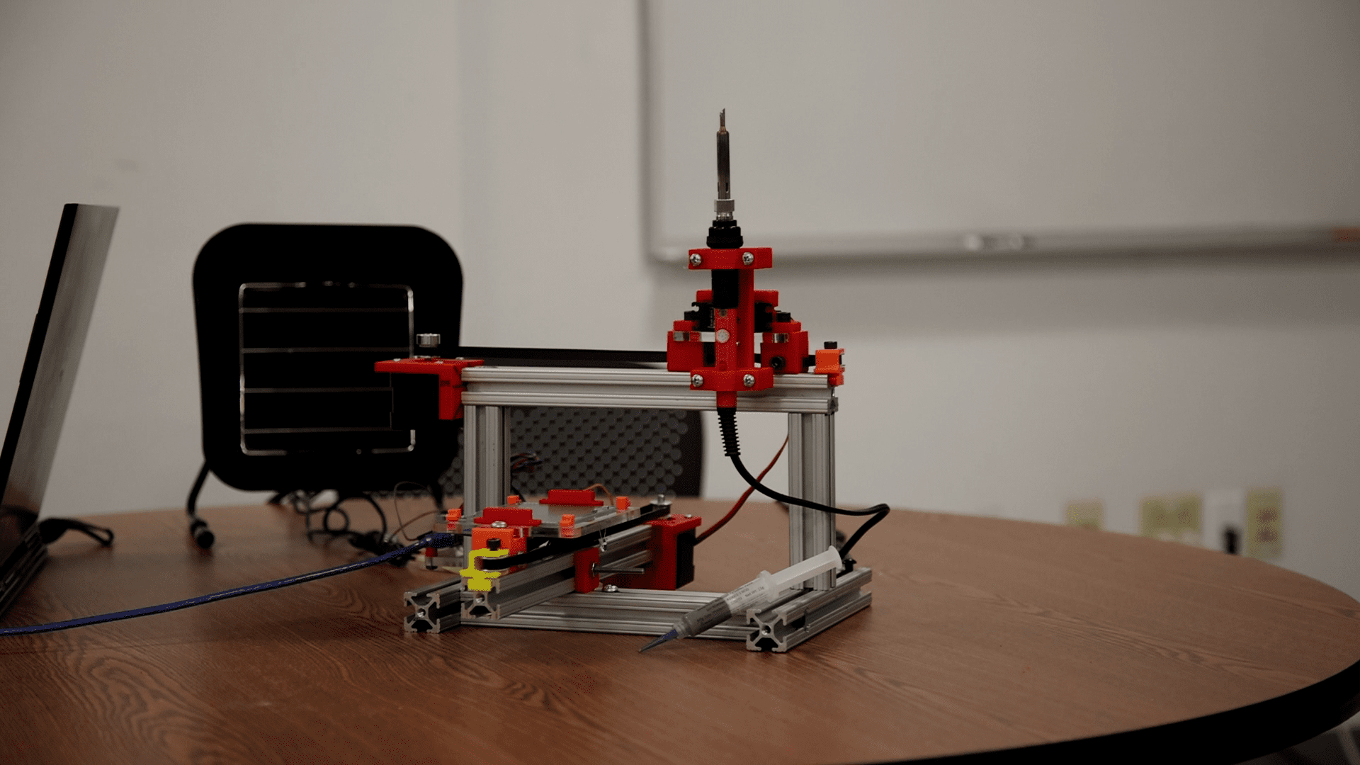
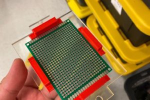
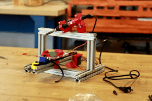
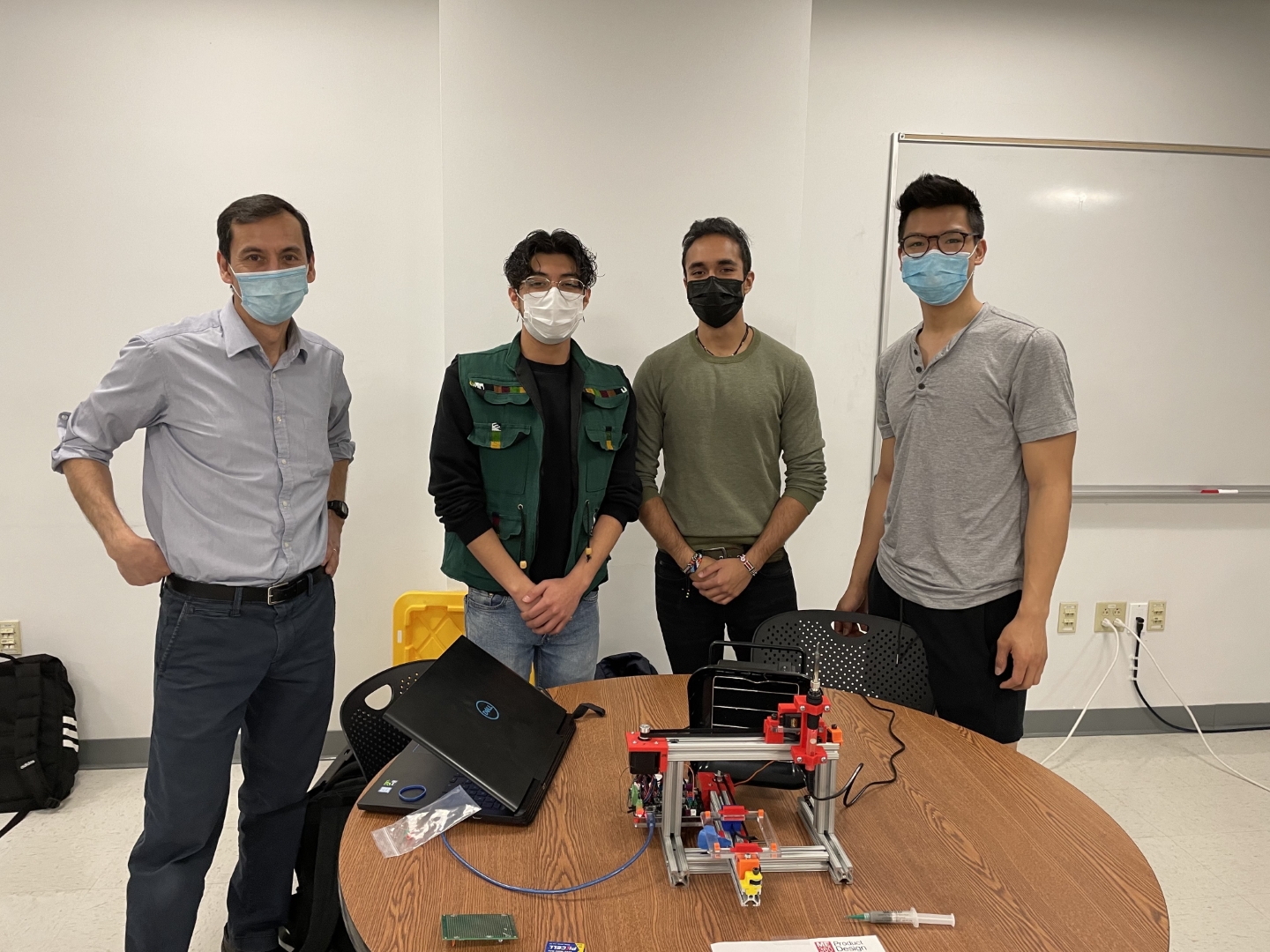
The Semi-Automatic Soldering Station is comprised of two belt-driven linear drive stages coupled with a servo motor actuator. It features modified off-the-shelf parts as well as custom 3-D printed and laser-cut parts. The machine can hold a 90 x 70 cm soldering board and can solder any pre-programmed layout with electronics and soldering paste pre-applied. In just a month, our team turned our conceptual ideas into a fully functioning machine with little setbacks.
Design Process Duration: 1.5 Weeks
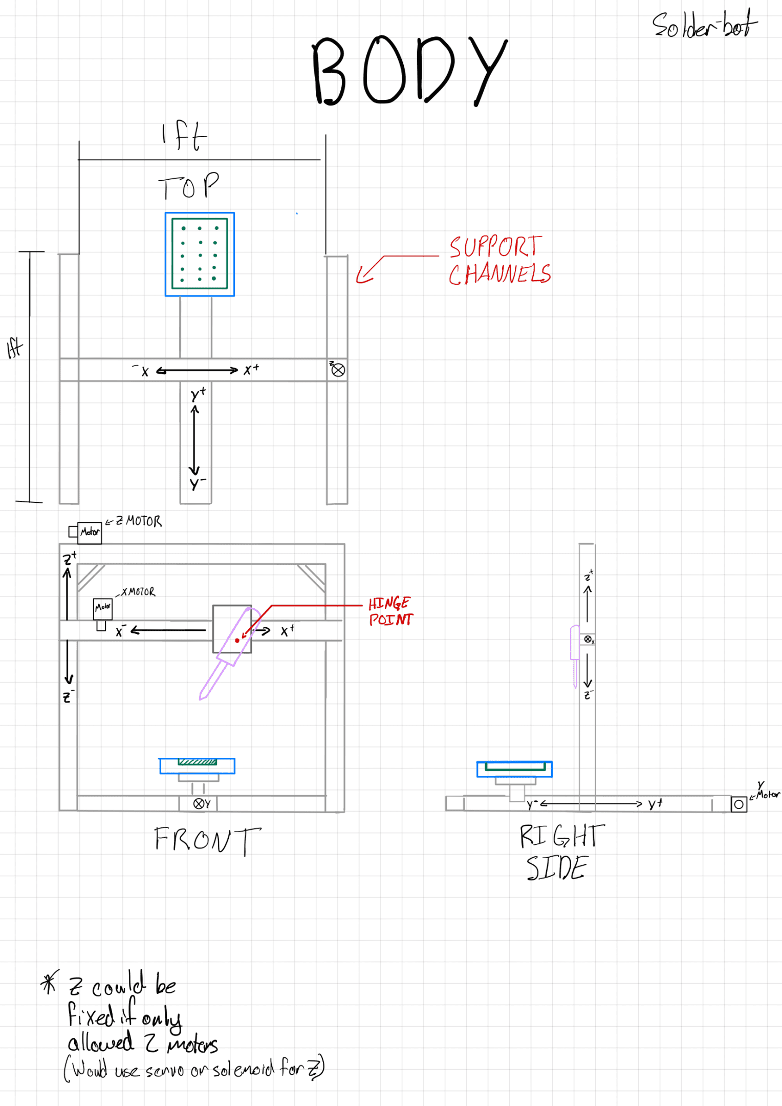
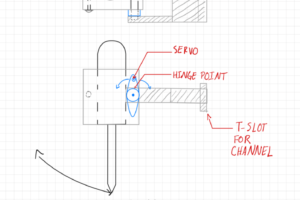
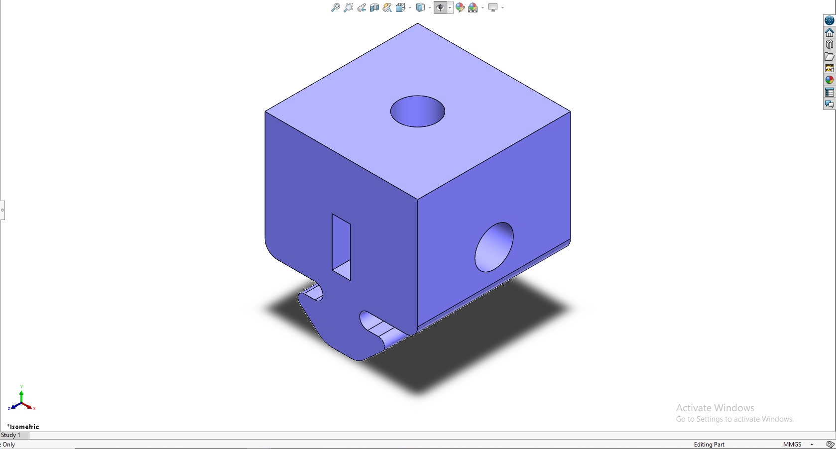
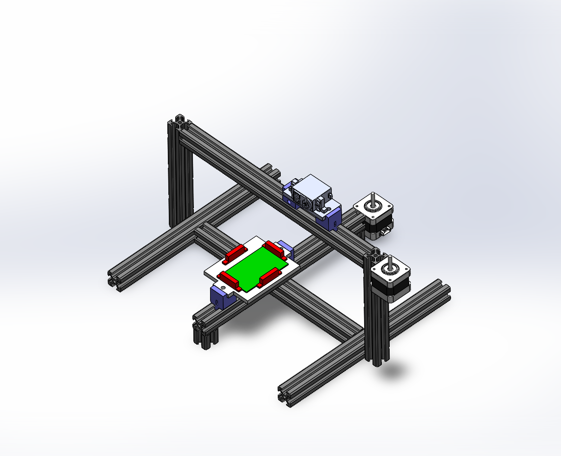
The project started with a simple idea and multiple visions from each member. On the left, our initial sketch of the general layout is shown, with detailed sketches of our parts. With most of the dimensions known, a preliminary CAD model of the assembly was created to visualize what the final product will be looking like.
The main driving factors for our design decisions were simplicity and ease of prototyping/assembling. Given the time constraints of the project, it was important for us to design for ease of manufacturability and fast iteration in case something went wrong. We also wanted to build a robust yet compact system that achieved its core functionalities really well.
Parts Fabrication Duration: 1 Week
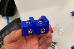
With all of our parts modeled, it was time to source or create them. For our linear drives, custom 3D-printed sliders were created with holes for mounting our brass 1/4″ screw inserts for the acrylic bases and the belt set screw. The bases for the soldering board, the actuator, and the control board were fabricated out of laser-cut clear 1/4″ acrylic. To mount the motors and the pulleys to the 80-20 aluminum extrusions, 3D-printed adapters were modeled and printed. Finally, the soldering iron was attached to the servo motor (actuator) via a 3D-printed holder directly attached to the servo shaft.
Validation Testing Duration: 1 Week
Once the linear drives were assembled, they had to be properly wired to our control board and calibrated. This is the stage where most of our issues came up as the 3D printed sliders would get caught on the 80-20 extrusions (bad prints) and the threaded screw inserts would not sit stationary on the plastic. After multiple iterations of perfecting the print for the sliders and running through the G-Code, the linear drives were functional.
Assembly Duration: 1.5 Weeks
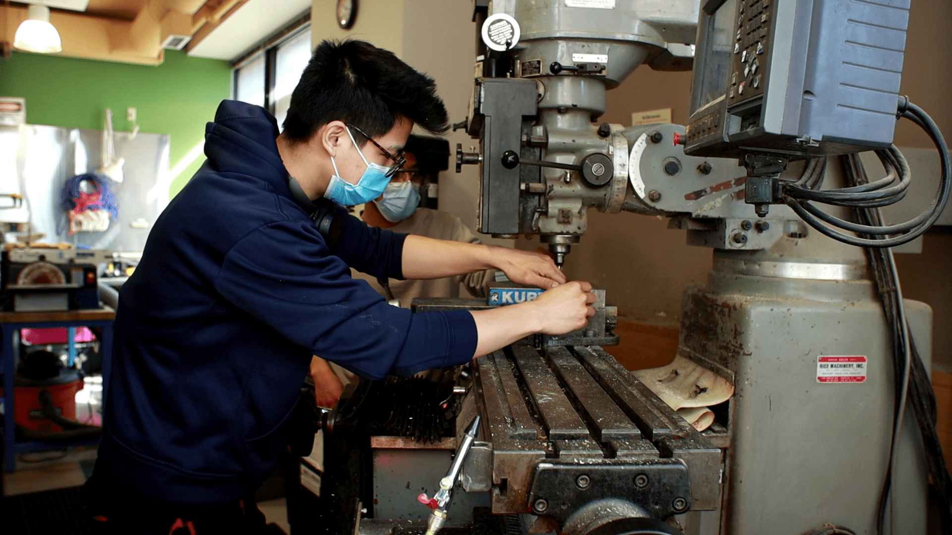
Once our individual components were tested and properly working, we started the assembly progress. As previously mentioned, we wanted the assembly to be compact and simple to put together. The 80-20 extrusions were cut to our desired dimensions and through careful measurements and machining operations, the extrusions fit near perfectly together.
With the physical system complete, we proceeded to code and synchronize each individual component with each other. We set up our demo soldering board with electronics and created pseudo-code to visualize the steps needed to make a program. We mapped out the layout of the soldering board and found the coordinates of each hole. We hit initial roadblocks trying to accurately map out the stepper motor steps to the distances needed to travel between solders. However, after observing the system’s behavior closely, we realized that the home position of our linear drives would change ever so slightly. For our final demo, we fixed the issue and got precise and accurate locations for our soldering iron to rotate down and do its job.
Future Improvements
While this system worked as expected, there are many features that can be included in the next iteration of the system. The most important one is a guided user interface (GUI) that allows the user to easily select the pins/holes that need to be soldered and automatically create the G-Code program based on the user’s needs. A second useful addition to the system would be a more versatile mounting solution for the soldering board. The current version can only hold a 90 x 70 cm board. We would like to be able to accommodate both bigger and smaller boards to make this system fully versatile.
